
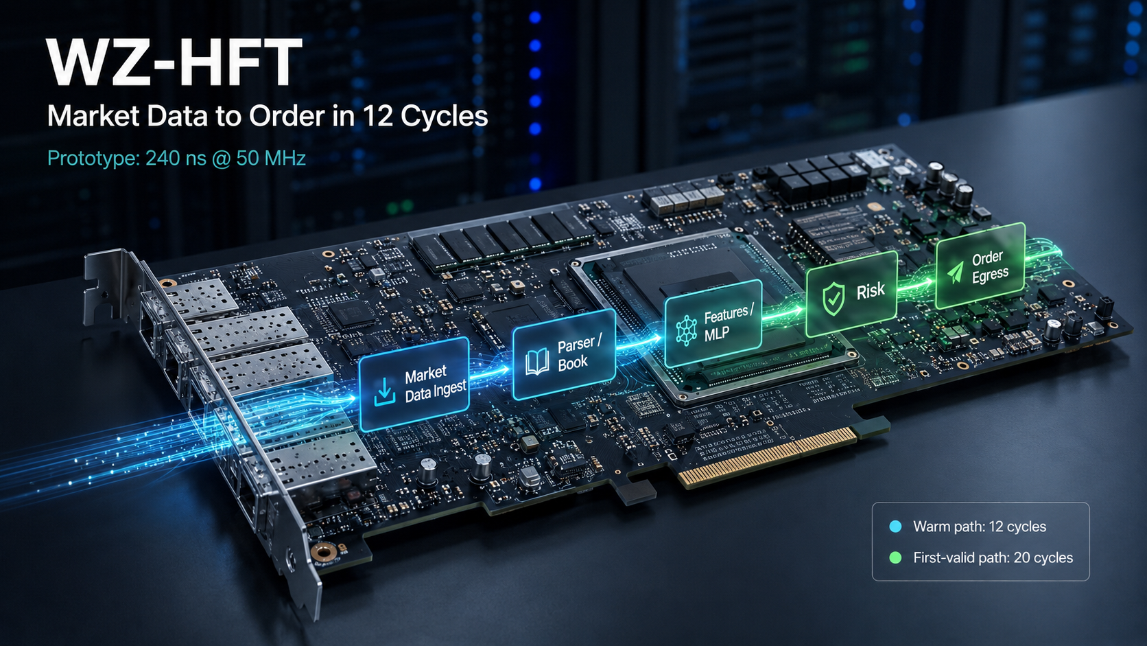
A warm market event crossed WZ-HFT, from the final received byte after CDC to the first generated order byte, in 12 clock cycles.
Four first-valid events took 20 cycles. That was not jitter. It was state.
The architecture is measured in cycles. The clock decides how long those cycles take.
We did not build a 240 ns architecture. We built a 12-cycle steady-state hardware trading path and first exercised it at 50 MHz. At that clock, twelve cycles occupy 240 ns. The same pipeline depth at 300 MHz corresponds to 40 ns before physical Ethernet latency is added.
The useful result was not one nanosecond number. It was discovering that the trading path itself is twelve clocks deep, and exactly what makes four initialization events eight clocks longer. Six warm trades took 12 cycles; four first-valid trades took 20.
One replay, two exact paths, no latency jitter
WZ-HFT tracks four symbols in this reference configuration: AAPL, MSFT, AMZN and GOOG. The first time each symbol acquires a valid best bid and offer, the feature path must wait for an eight-cycle imbalance calculation. That happens once per symbol. Later BBO changes already have a registered imbalance value available and enter the warm path immediately.
| Event class | Count | Cycles | At 50 MHz | Why |
|---|---|---|---|---|
| Warm BBO update | 6 | 12 | 240 ns | Registered imbalance already available |
| First-valid BBO | 4 | 20 | 400 ns | Fixed eight-cycle divider initialization |
| Replay total / mean | 10 | 152 / 15.2 | 304 ns mean | Exactly six warm plus four first-valid events |
Only two latency values occur in this workload: 12 and 20 cycles. The 152-cycle sum identifies their distribution exactly.
The 20-cycle result is the 12-cycle path plus one fixed eight-cycle dependency. It is state-dependent latency, not noise.
The 12-cycle trade, cycle by cycle
The counter begins when the final market-data byte has crossed the receive CDC boundary. Four cycles later, parsing and book state have produced the BBO change. The hardware feature and three-layer MLP path reaches order fire at cycle 10. Risk clears at cycle 11; the first transmit byte appears at cycle 12.
cycle  0  final market-data byte arrives after RX CDC
cycle  4  parser -> book update -> BBO change detected
cycle 10  feature capture -> MLP L1 -> L2 -> L3 -> order fire
cycle 11  risk engine clears
cycle 12  first generated TX byte
Warm path: final byte after RX CDC to first generated TX byte.
This is the path that matters after initialization. The CPU configures and observes the datapath; it is not in the per-message critical path. Parsing, state, inference, risk and order egress remain in deterministic hardware.
Where the other eight cycles come from
One feature is imbalance: bid quantity divided by total quantity. On the first valid BBO for a symbol there is no previous result in the register. The current implementation waits for the eight-cycle divider to produce it, then launches the same feature and MLP path used by a warm event.
cycle  0  final market-data byte arrives after RX CDC
cycle  4  first valid BBO for this symbol
cycles 4-12  wait for initial imbalance result
cycle 12  imbalance ready; feature capture begins
cycle 18  MLP completes; order fire
cycle 19  risk engine clears
cycle 20  first generated TX byte
Cold path: exactly eight cycles longer, once for each of four tracked symbols.
The useful question is therefore not “why did latency jitter?” It is “does the first decision require a fresh divide?” That is an architectural choice with three concrete answers: initialize imbalance to a neutral registered value and update it in parallel, replace the iterative divide with a faster reciprocal pipeline, or remove imbalance from the model features. Each changes either feature freshness, resource cost or strategy semantics. Each can be measured.
Twelve cycles travel; nanoseconds belong to the clock
The prototype clock was 50 MHz, so every cycle occupied 20 ns. That makes the warm path 240 ns and the first-valid path 400 ns. If the same 12-cycle pipeline closes unchanged at a higher frequency, the time per cycle falls:
| Core clock | Cycle period | 12-cycle warm path | 20-cycle first-valid path |
|---|---|---|---|
| 50 MHz | 20 ns | 240 ns | 400 ns |
| 100 MHz | 10 ns | 120 ns | 200 ns |
| 200 MHz | 5 ns | 60 ns | 100 ns |
| 250 MHz | 4 ns | 48 ns | 80 ns |
| 300 MHz | 3.333 ns | 40 ns | 66.7 ns |
| 400 MHz | 2.5 ns | 30 ns | 50 ns |
The 50 MHz row is the demonstrated prototype conversion. Higher-frequency rows are cycle-to-time projections, not achieved hardware results.
This is why cycles are the portable architectural result. A new implementation still has to close timing and preserve the same pipeline, but it does not have to rediscover the architecture. It gives the existing stages less time to occupy.
What the prototype proved, and what the next platform adds
The reference design was driven by adapted historical Nasdaq TotalView-ITCH data. Ten eligible events produced ten transmit frames, with zero observed RX CDC drops and zero TX overflow. BoardSim and the FPGA counters agreed on the cycle accounting. More importantly, the run exposed the two latency classes and the precise dependency that separates them.
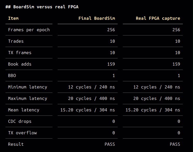
Final BoardSim versus physical FPGA capture. The workload counts and latency registers agree: 256 frames, 10 trades, 10 TX frames, 12/20-cycle minimum/maximum, 15.2-cycle mean, zero CDC drops and zero TX overflow.
The next platform does not replace the 12-cycle result. It extends it: a faster fabric clock shortens the core time, while native high-speed Ethernet makes the additional receive and transmit latency visible. The complete measurement becomes:
PHY/PCS latency is additive around the measured core. It does not erase the core cycle count.
HFT was the workload; the reference SoC was the test
WZ-HFT is a trading reference SoC built to force reusable IP to work as a system. The workload combines market-data parsing, an order book, feature generation, an ML decision path, hardware risk, a RISC-V control plane, CDC, replay, counters and transmit generation. Every unnecessary cycle becomes visible, and every weak interface eventually becomes a system problem.
That is why we build reference SoCs around serious workloads. An isolated RISC-V core can pass an instruction test. An accelerator can pass a vector. A protocol block can emit a valid frame. Only a system makes them share clocks, state, memory, software, backpressure and a measurable outcome.
The HFT experiment did more than produce a latency number. It showed exactly where the CPU should leave the critical path, exactly where an eight-cycle feature dependency remained, and exactly what the next implementation must preserve. The next gate is direct: make every eligible event a validated 12-cycle event, close that path at the higher target clock, then measure the added physical Ethernet latency independently from wire to wire.
It is a 12-cycle steady-state trading pipeline first demonstrated at 50 MHz.
The prototype established the path. The next platform shortens the clock and measures the wire around it.